Electrical Design for the PLAYER
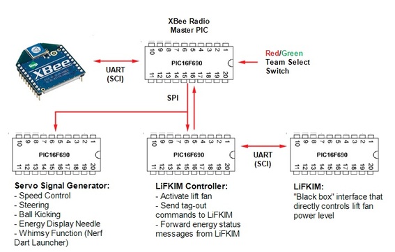
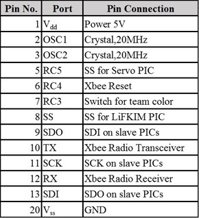
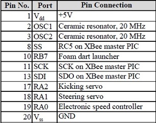
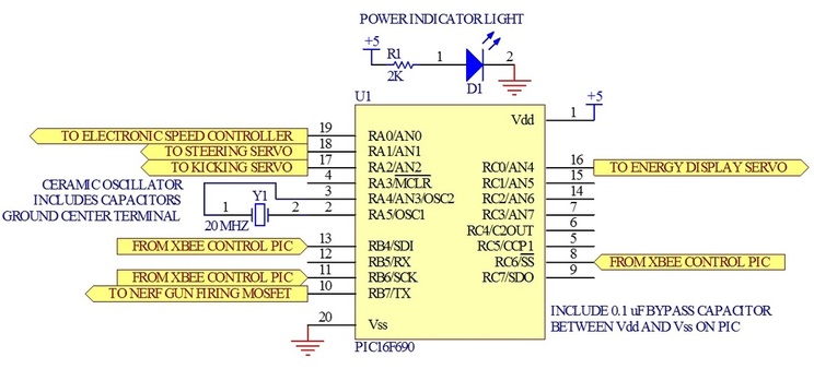
The mobile hovercraft platform, also known as the PLAYER, was designed around four PIC microcontrollers and an XBee radio transceiver. The interprocessor communications network and task breakdown on the PLAYER is depicted in the diagram below. The Master PIC is responsible for decoding messages sent wirelessly from the COACH (controller) and forwarding the commands to other PICs via an SPI protocol. The Master PIC is also responsible for sending "heartbeat" status updates back to the COACH. The Servo Signal Generator is used for controlling speed, steering, kicking, energy display, and "whimsy" functions. Steering, kicking, and the movement of an energy display pointer are all implemented with servo motors. A DC brushless motor (attached to a propeller) is used for propulsion; the electronic speed control unit for this motor is also driven by a standard servo signal (1-2 ms active high pulse width, 20 ms period). Teams were given the option of implementing a "whimsy" function on their hovercrafts that would serve no useful purpose other than entertainment of the audience. Team 12 opted for a Nerf dart turret that would fire foam darts into the audience (at low elevations and velocities to ensure safety, of course). The LiFKIM Controller was programmed in assembly code per project requirements and served the purpose of forwarding lift and tag-out commands to the LiFKIM (Lift Fan Kontroller [sic] and Impact Monitor). It was also responsible for parsing response messages from the LiFKIM and forwarding energy status updates back to the Master PIC. The LiFKIM itself was a "black box" as far as the team was concerned and implemented a PWM output, via a power MOSFET, to drive the lift fan.
Circuits on the PLAYER
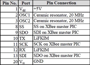
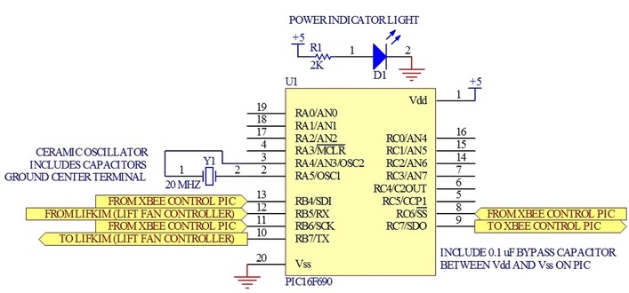
XBee Radio Transceiver Board

Motor Control Board
LiFKIM (Lift Fan and Impact Monitor) Control Board
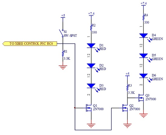
Team Color Selection/Indication Circuit
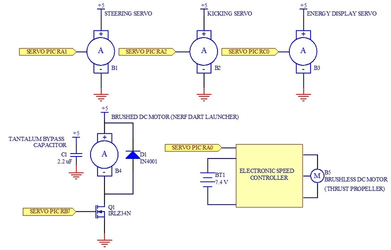
Motor Wiring
Power Supply
Electrical Design for the COACH
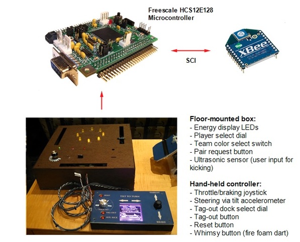
The wireless control unit, also known as the COACH, was based on a Freescale HCS12E128 microcontroller and an XBee radio transceiver. The COACH consisted of a floor-mounted box which housed the microcontroller, power supply, and radio control unit. This box also presented a number of user inputs that would be required for initial pairing with a PLAYER. On the side of the box was an ultrasonic sensor that the user could swing a foot past in order to send a ball kicking command to the PLAYER. When paired, the top of the box displayed a circulating pattern of yellow LEDs to indicate the current energy state of the PLAYER. A hand-held controller was also provided for user inputs that would require continuous updating (e.g., steering and throttle).
Circuits on the COACH (Handheld Controller)
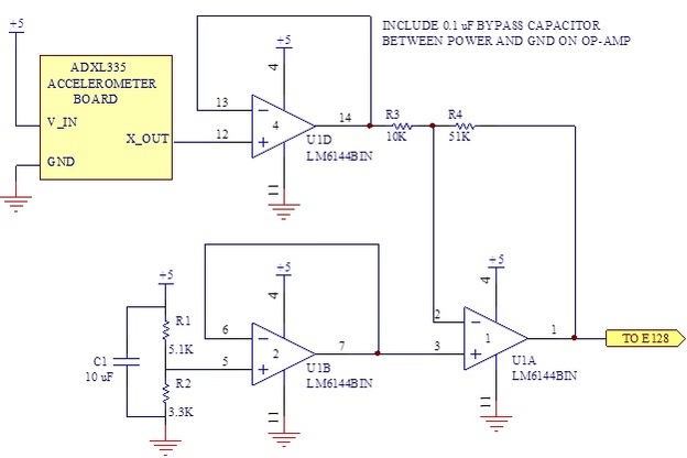
Accelerometer Tilt Sensor for Steering Input
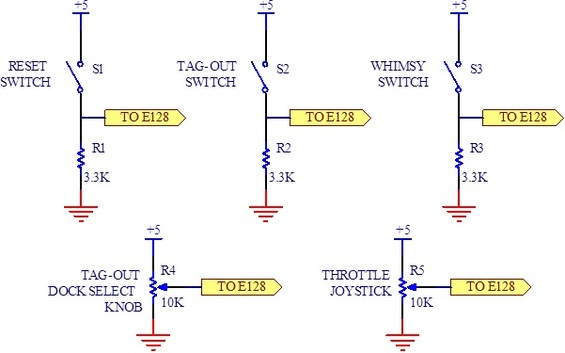
Switch and Dial Array for User Input
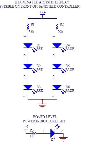
Artistic Display Illumination and Indicator Lights
Circuits on the COACH (Floor-Mounted Box)
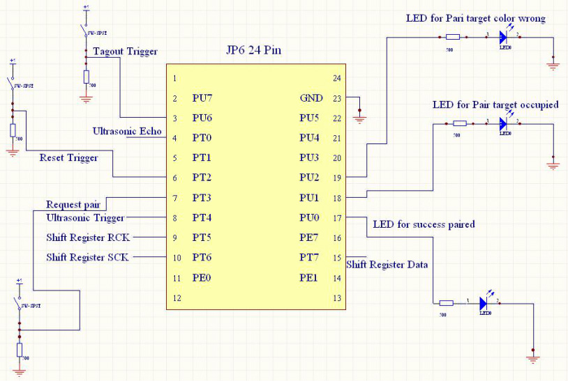
HCS12E128 Microcontroller (JP6 Connector)
The tag-out trigger, reset trigger, and pair request trigger are straightforward as they all consist of SPST (normally-open, momentarily-closed) switches. For kicking, an ultrasonic sensor is installed on the right side of the box. Based on the ultrasonic echo signal, the controller will transmit either a "Kick" or "No Kick" command to the PLAYER.
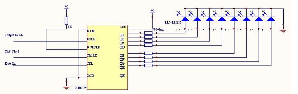
There are also three LEDs indicating whether or not a pair request with a selected player is successful. If the request is not successful, the LEDs will indicate the type of error. Lastly, a shift register is used to control a circulating pattern of eight large LEDs to communicate the current energy status of the PLAYER to the user. Circuit schematics are shown below.
There are also three LEDs indicating whether or not a pair request with a selected player is successful. If the request is not successful, the LEDs will indicate the type of error. Lastly, a shift register is used to control a circulating pattern of eight large LEDs to communicate the current energy status of the PLAYER to the user. Circuit schematics are shown below.
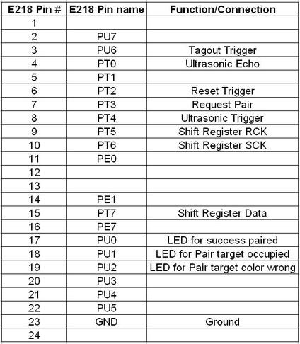
Pin-out for HCS12E128 Microcontroller (JP6 Connector):
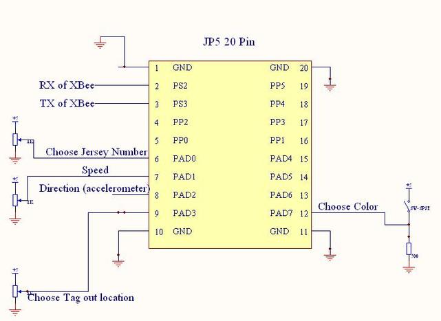
HCS12E128 Microcontroller (JP5 Connector)
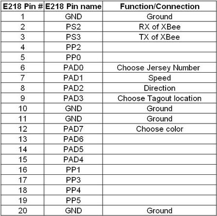
Three potentiometers are provided for selecting PLAYER jersey number (during a pair request), speed, and intended tag-out location. To turn, the handheld portion of the COACH contains an accelerometer that outputs an analog voltage in response to being tilted to the left or right. A digital switch is used to select the team color (red or green) during a pair request.
Pin-out for HCS12E128 Microcontroller (JP5 Connector):
Shift Register Controlling LED Display of the LiFKIM Energy Level
Calculation of Battery Life for the COACH
Upon review of the datasheets for the parts used in the COACH, the following current draws are expected for the main components:
HCS12E128 microcontroller: 65 mA (typical)
XBee radio transceiver: 70 mA (max)
Shift register circuit (8 LEDs with 500 ohm resistors): 8*(5V/500 ohm) = 80 mA
3 LEDs with 500 ohm resistors - 3*(4.5V/500 ohm) = 27 mA
Total Current Draw (At 5V with all LEDs on): ~250 mA
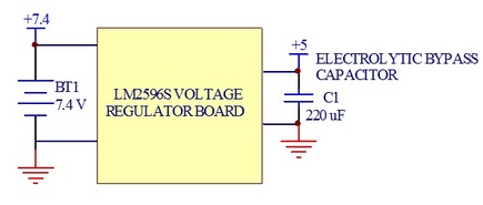
The 5V power supply on the COACH is provided by a voltage regulator with ~70% efficiency. Upstream of the voltage regulator are two 7.4 V, 1800 mAh NiCad batteries wired in series. Thus the input voltage to the voltage regulator is nominally 14.8 V. The current draw out of the batteries may be approximated as:
Total Current Draw (From 14.8 V battery source): (5V/14.8V)*(1/70%)*250 mA = ~125 mA
Finally, the expected battery life may be calculated based on the current draw and charge capacity of the batteries:
EXPECTED BATTERY LIFE: (1800 mAh/125 mA) = ~14 HOURS
These calculations indicate that the COACH easily surpasses the requirement for eight hours of battery life.
HCS12E128 microcontroller: 65 mA (typical)
XBee radio transceiver: 70 mA (max)
Shift register circuit (8 LEDs with 500 ohm resistors): 8*(5V/500 ohm) = 80 mA
3 LEDs with 500 ohm resistors - 3*(4.5V/500 ohm) = 27 mA
Total Current Draw (At 5V with all LEDs on): ~250 mA
The 5V power supply on the COACH is provided by a voltage regulator with ~70% efficiency. Upstream of the voltage regulator are two 7.4 V, 1800 mAh NiCad batteries wired in series. Thus the input voltage to the voltage regulator is nominally 14.8 V. The current draw out of the batteries may be approximated as:
Total Current Draw (From 14.8 V battery source): (5V/14.8V)*(1/70%)*250 mA = ~125 mA
Finally, the expected battery life may be calculated based on the current draw and charge capacity of the batteries:
EXPECTED BATTERY LIFE: (1800 mAh/125 mA) = ~14 HOURS
These calculations indicate that the COACH easily surpasses the requirement for eight hours of battery life.
