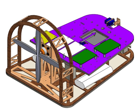
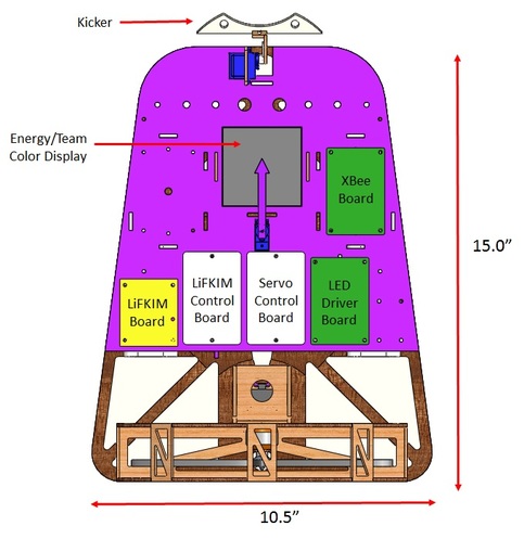
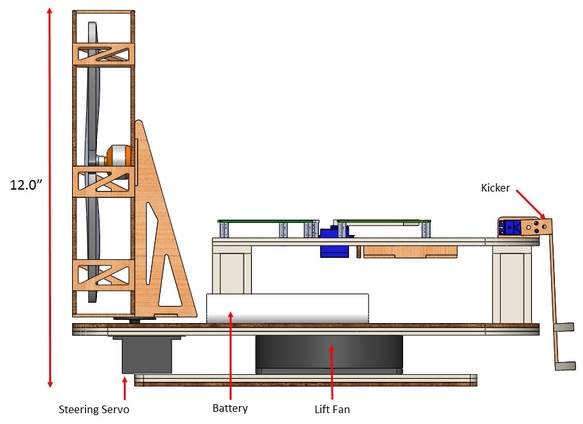
Mechanical Design for the PLAYER
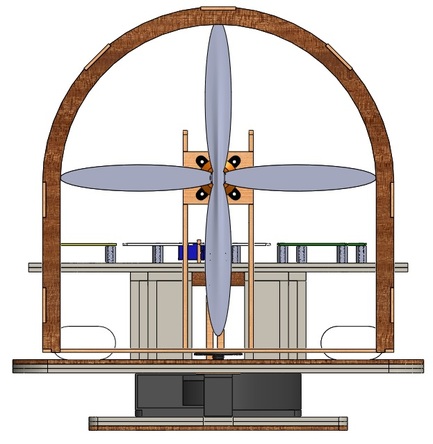
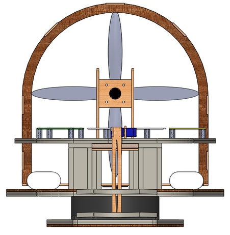
The PLAYER was designed with low weight and high speed in mind. Minimizing weight was the most direct way to increase the acceleration and reduce floor drag of the vehicle. Weight was minimized by using foamboard and balsa wood wherever possible. Where basswood or duron/masonite was necessary, truss structures were utilized to provide a high strength-to-weight ratio Thrust was maximized by selecting the largest propeller (9" diameter) that could integrated without exceeding the maximum 12" stack height given in the project specifications. Steering is accomplished by a single heavy-duty servo motor that rotates the thrust motor mounting bracket. Power is supplied by two 7.4 V, 1800 mAh batteries. One battery is used to power the lift fan while the second is used to power the thrust motor and all other electronics. A small servo motor is used to rotate a pointer arrow above an illuminated display to provide indication of both the vehicle's energy level and team color. Kicking of a plastic ball is provided by a servo-actuated kicking arm. Not shown in the isometric view below, a working foam dart launcher is mounted on the port side of the hovercraft to provide whimsical entertainment to the pilots and audience.
Mechanical Design for the COACH (Handheld Controller)
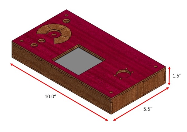
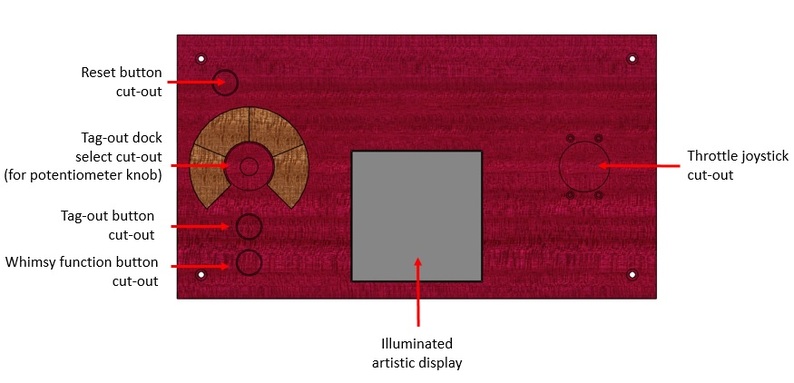
The handheld controller portion of the two-piece COACH consisted of a 10" x 5.5" x 1.5" duron box which housed circuits for steering, throttle, tag-out, whimsy function, and reset commands from the user. The center of the box also displayed a prominent, illuminated artistic rendering of our team's "hovercraft company logo". The user inputs for whimsy function, reset, and tag-out were provided by panel-mounted pushbuttons. Selection of the desired tag-out dock was provided by a panel-mounted potentiometer. Throttle and braking commands were implemented with a joystick potentiometer. Lastly, steering commands were set by tilting the box left or right (and sensed by an accelerometer). This handheld unit was wired to the floor-mounted COACH box which housed the HCS12E128 microcontroller and XBee radio transceiver.
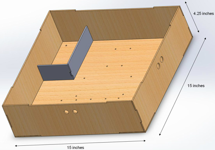
Mechanical Design for the COACH (Floor-Mounted Box)
The floor-mounted piece of the COACH is a box containing the E128, batteries, power supply management, and several auxiliary circuits. On the front side of the box, there are two feed-through holes for cords connecting to the handheld controller. The circuit boards are placed close to these two holes. The ultrasonic sensor is attached to two holes on the right side of the box. When a user wants to send a command for kicking, he or she must simply kick in front of the ultrasonic sensor.
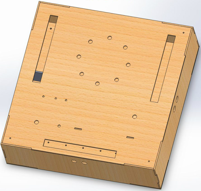
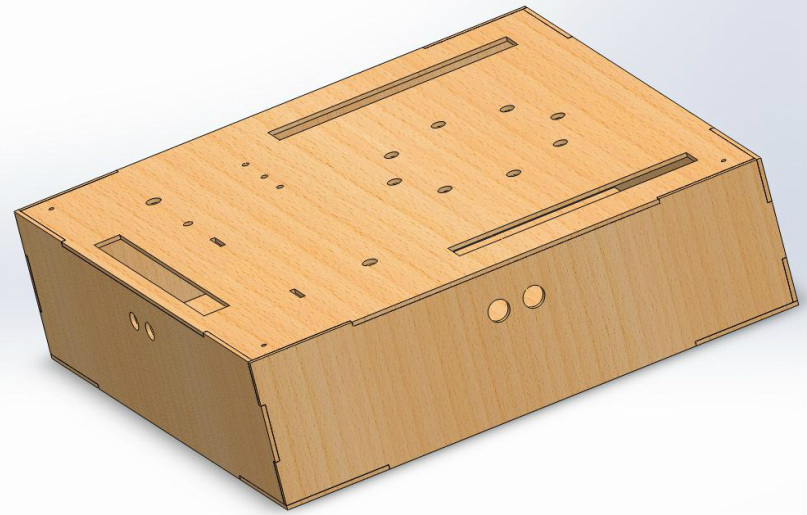
Inside the box, the batteries are placed in the top-left corner. The power management module is put right next to it so that it is easy to hook up.